

I apologize if this has been reported before, but I couldn't find mention of it.
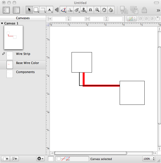
I am trying to produce a wiring diagram. The wires are color coded with a base color and a stripe. Since there appears to be no way to control the internal color of a double stroked line, I opted to put the base color on one layer then layout an identical line over it with the strip color. I use 6pt ortho line on the base layer, and 2 point ortho line on the strip layer. Aside from the extra effort, it work fine except at the line ends.
When I put a stripe line over the base line the base line is not drawn all the way to the component.

If I shift the end point of the stripe line over one magnet, then the base line is drawn correctly.
I have attached PNGs of the problem, as well as a demo graffle file.
Is there a work around?
I have found one work around: draw the line in the opposite direction. The strip line is drawn in the opposite sense form the base line, then the gap doesn't appear.
I am trying to produce a wiring diagram. The wires are color coded with a base color and a stripe. Since there appears to be no way to control the internal color of a double stroked line, I opted to put the base color on one layer then layout an identical line over it with the strip color. I use 6pt ortho line on the base layer, and 2 point ortho line on the strip layer. Aside from the extra effort, it work fine except at the line ends.
When I put a stripe line over the base line the base line is not drawn all the way to the component.
If I shift the end point of the stripe line over one magnet, then the base line is drawn correctly.
I have attached PNGs of the problem, as well as a demo graffle file.
Is there a work around?
I have found one work around: draw the line in the opposite direction. The strip line is drawn in the opposite sense form the base line, then the gap doesn't appear.
Last edited by enderw88; 2011-10-16 at 02:44 PM..
 Linear Mode

